Fast and Accurate Trajectory Tracking for UAV based on DRL
Motivation
- With the increasing of data volume and accuracy requirements for practical applications, the
stable autonomous guidance and controlhave been considered as one of the most critical. - Efficient tracking algorithms enable a
smooth trajectoryand hence alower system power dissipationduring the flight. PIDcontroller works well when process dynamics arebenignand the performance requirements aremodest.- Due to UAV
multi degrees of freedom, tracking methods based on conventional control theory such asPIDhas limitations:response time: can not treat processes withlarge time delayefficiently.adjustment robustness: it shows poor performance for tracking problems requiringaggressive dynamicconfigurations, includinguncertain internal disturbance compensationand imbalances retrieval.
Model based approachthat calculates the force and torques based on UAV’s current status iscomplicated and rigid.- It is hard to obtain a high fidelity
mathematical modelof a UAV which has anunder-actuatedsystem withnonlinear dynamics. - To improve the
stability and real-time control,DNNembedded on different hardware platforms. - Through large data training, the
DNN-based controlsystem achievesadaptabilityandrobustnessthat guarantee the stability of the flight with thetolerance of unexpected disturbance.
Contributions
- Present an actor-critic RL framework that controls UAV trajectory through a set of desired waypoints.
- A deep neural network is constructed to learn the optimal
tracking policy. RLis developed to optimize the resulting tracking scheme.- Implement using FPGA, one single decision can be made within
0.0002sat only0.03mWpower consumption in a decision epoch. - Experimental results:
- less position error.
- less system power consumption.
- faster attainment.
Method
Trajectory Generation
Waypointsare generated considering:- the actuator locations on the body of the quadrotor.
obstacles and potential collisionhazards detected in the field of view of the onboard sensors.
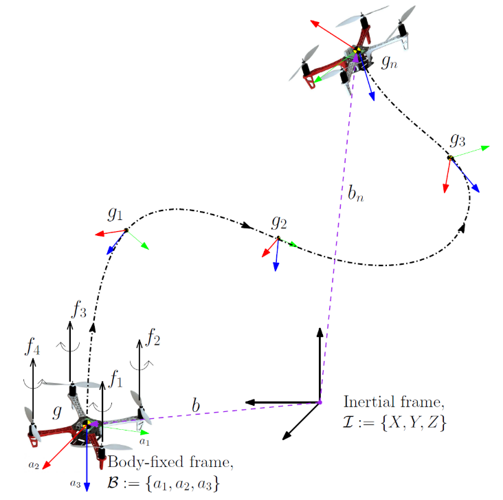
Trajectory generation:- After waypoints are selected, a \(C^2\) trajectory is generated for the desired inertial position in time to connect these waypoints.
- \(C^2\): continuous and twice differentiable w.r.t. time.
- \(p_{d_t}\): position.
- \(\dot{p}_{d_t}\): translational velocity.
- \(\ddot{p}_{d_t}\): desired translational acceleration.
- \(R_{d_t}\): desired attitude.
- \(f_{d_t}\): desired UAV control thrust.
- After waypoints are selected, a \(C^2\) trajectory is generated for the desired inertial position in time to connect these waypoints.
Trajectory Tracking
Goal: minimize the differences betweendesired posesandactual posesduring tracking.Desired state(18D): \(S_{d_t} = \{ p_{d_t}, v_{d_t}, a_{d_t}, R_{d_t} \}\).Actual State(18D): \(S_t = \{ p_t, v_t, a_t, R_t \}\).
State
\[\mathbb{S}_t = \{ S_{d_t}, S_t \}.\]Action
\[\mathbb{A}_t = \{ f_t, \tau_t \}.\]Reward
- Minimize the
distancebetween the desired position and actual position. - The
stabilityof the quadrotor. - Simply using a
linear combinationof \(\Delta P_t, \Delta V_t, \Delta R_t\) as the reward function will makeconvergence difficultin learning process. - Using
geometrically discounted rewardwill prevent the accumulated reward to become infinite and make the model more tractable.- Therefore, define the reward at each time step following a
standard normal distribution.- Thus, guaranteeing the
largest rewardis accepted when the total differences between desired trajectory and actual trajectory at time \(t\) reaches \(0\). - And the reward closing to \(0\) when the
total differences increase.
- Thus, guaranteeing the
- Therefore, define the reward at each time step following a
Then, the total discounted reward is:
\[\mathbb{R} = \sum_{t=0}^\infty \gamma^t R_t.\]DNN
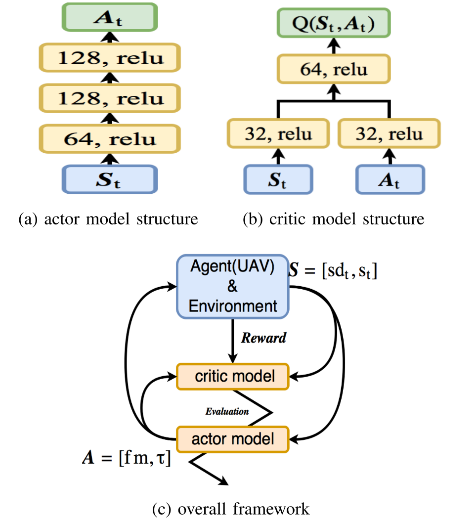
- The actor model is pre-trained using
labeledpair data \((\mathbb{S}_t, \mathbb{A}_t)\).
Experiment
Hardware Configuration
FPGA: all massive parallel computations are implemented on it.- DSP blocks are used as multiplier.
- Implement DNN controller (actor model).
- Output
control commands.
ARM: low-level control.- Takes
control commandsfrom FPGA as input. - Calculates actuations in each freedom.
- Sends actuations to UAV and accepts flight states and sensor data from UAV via
UART.
- Takes
PID Implementation (baseline)
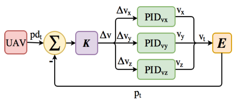
- Three PID controller are used for each component of velocity respectively.
- Calculate errors of each component between
desired velocityandachieved velocity.
- Calculate errors of each component between
- The
achieved position\(p_t\) is calculated through environment simulation and used asfeedbackon current velocity.
Evaluation
- L1-Norm of
position tracking error. - L1-Norm of
velocity tracking error. Timeused to complete tracking.Powerconsumption.Robustness: tracking in a noisy environment.- Add different levels of random Gaussian noise on the position (such noise could be used to model the effect of wind gust).
References
- Y. Li et al., “Fast and accurate trajectory tracking for unmanned aerial vehicles based on deep reinforcement learning,” IEEE 25th International Conference on Embedded and Real-Time Computing Systems and Applications, RTCSA, 2019.