Trajectory Planning for Quadrotor Flight Through Narrow Gaps
Framework
Split the whole trajectory planning into two consecutive stages:
- Compute a
traverse trajectoryto pass through the gap.Maximize the distancefrom the vehicle to the edges of the gap, in order to minimize the risk of collision.
- Compute an
approach trajectoryin order to fly the quadrotor from its current hovering position to the desired state that is required to initiate the traverse trajectory.- Satisfy
perception constraints, let the vehicle-mounted camera always face the gap, which is necessary to enable state estimation w.r.t. the gap.
- Satisfy
Both trajectories need to satisfy dynamic constraints.
Traverse Trajectory
Goal: Minimize the risk of collision.
Solution:
- Force the traverse trajectory to intersect the center of the gap.
- Simultaneously lying in a plane orthogonal to the gap.
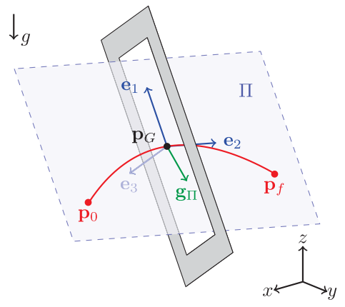
- \(W\): world frame.
- \(\mathbf{p}_G\): position of the geometric center of the gap.
- \(\mathbf{R}_G\): orientation of the gap w.r.t. \(W\).
- \(\Pi\): the plane orthogonal to the gap.
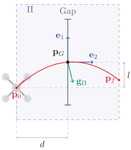
- Passing through the gap’s center.
- Parallel to the longest side of the gap.
- \((\mathbf{e}_1,\mathbf{e}_2,\mathbf{e}_3)\): orthogonal basis of the plane.
- \(l\): the distance between \(\mathbf{p}_G\) and \(\mathbf{p}_0\) along \(\mathbf{e}_1\).
- \(d\): the distance between \(\mathbf{p}_G\) and \(\mathbf{p}_0\) along \(\mathbf{e}_2\).
- Determined through an optimization problem.
Polynomial of the trajectory
The projection of the gravity vector \(\mathbf{g}\) onto \(\mathbf{e}_3\):
\[\langle\mathbf{g},\mathbf{e}_3\rangle\mathbf{e}_3 = \mathbf{e}_3^T \mathbf{g}\mathbf{e}_3.\]Then, the remain components of \(\mathbf{g}\) in plane \(\Pi\) can be computed as:
\[\mathbf{g}_\Pi = \mathbf{g} - \mathbf{e}_3^T \mathbf{g}\mathbf{e}_3.\]The motion of the quadrotor along \(\Pi\) is described by (ballistic trajectory):
\[\begin{aligned} p_i(t) & = p_i(t_0)+v_i(t_0)t+\frac{1}{2}g_{\Pi,i}t^2, \\ v_i(t) & = v_i(t_0)+g_{\Pi,i}t. \end{aligned}\]Where \(i=1,2\) indicates the motion along \(\mathbf{e}_i\) axis.
- The motion is a uniformly accelerated along both \(\mathbf{e}_1,\mathbf{e}_2\).
- When \(g_{\Pi,2} = 0\), the quadrotor moves on a parabola in space.
The initial position and velocity can be computed by:
\[\begin{aligned} \mathbf{p}_0 & = \mathbf{p}_g - (l\mathbf{e}_1+d\mathbf{e}_2), \\ \mathbf{v}_0 & = \left( \frac{l}{t_c} - \frac{1}{2}g_{\Pi,1}t_c \right)\mathbf{e}_1 + \left( \frac{d}{t_c} - \frac{1}{2}g_{\Pi,2}t_c \right)\mathbf{e}_2. \end{aligned}\]Where \(t_c = \sqrt{\frac{-2l}{g_{\Pi,1}}}\) is the time necessary to reach the center of the gap, ensure that \(\mathbf{v}\) along \(\mathbf{e}_1\) is \(0\) at the center of the gap.
Therefore, the 3D trajectory has the following form:
\[\begin{aligned} \mathbf{p}(t) & = \mathbf{p}_0 + \mathbf{v}_0 t + \frac{1}{2}\mathbf{g}_{\Pi}t^2, \\ \mathbf{v}(t) & = \mathbf{v}_0 + \mathbf{g}_\Pi t, \\ \mathbf{a}(t) & = \mathbf{g}_\Pi. \end{aligned}\]Optimization of the trajectory
Problem: An error in the initial position is propagated through time according to the polynomial, then may lead to a collision.
Solution: Reduce the time duration \(t_c\) of the traverse trajectory to reduce the risk of impact.
Then, we can optimize the value of \(l\) to reduce the time duration.
But, reduce \(t_c\) leads to an increase of the initial velocity \(\mathbf{v}_0\).
And, the initial velocity \(\mathbf{v}_0\) depends on \(d\).
The value of \(d\) cannot be chosen small, because:
- Guarantee a safety margin between the quadrotor and the gap.
- Ensure the gap in the view of the camera.
The optimization problem is formulated as:
\[\min_{d,l} t_c,\] \[s.t.\begin{cases} \Vert \mathbf{v}_0\Vert \le v_{max}, \\ d\ge d_{min}. \end{cases}\]Solve the nonlinear optimization problem with Sequential Quadratic Programming (SQP).
- Using the NLopt library.
- Solved onboard in few tens of milliseconds.
Approach Trajectory
Goal:
- Match the initial conditions of the traverse trajectory.
- The end position, velocity, and acceleration of the approach trajectory are \(\mathbf{p}_0, \mathbf{v}_0,\mathbf{a}_0\).
- Enable robust perception and state estimation w.r.t. the gap.
- Keep the gap in the field of view of a forward-facing camera onboard the quadrotor.
Solution:
- Compute trajectory candidates.
- Polynomial trajectories.
- Evaluate the suitability for the given perception task.
Yaw angle planning
According to differentially flat, the yaw angle of the quadrotor can be controlled independently of the position and its derivatives.
Goal: Compute the yaw angle such that a camera mounted on the quadrotor always faces the gap.
- The camera should be oriented such that the center of the gap is projected as close as possible to the center of the image.
- \(\mathbf{p}_C\) is the camera’s position.
- \(\mathbf{R}_C = (\mathbf{r}_1,\mathbf{r}_2,\mathbf{r}_3)\) defines the camera orientation.
- \(\mathbf{r}_3\) is the camera’s optical axis.
Define the vector:
\[\mathbf{d} = \mathbf{p}_G - \mathbf{p}_C.\]Then, align the camera’s optical axis \(\mathbf{r}_3\) with vector \(\mathbf{d}\).
Because the trajectory constrains the quadrotor’s vertical axis \(\mathbf{z}_b\), we can only minimize the angle between \(\mathbf{d}\) and \(\mathbf{r}_3\) by solving the following constrained optimization problem:
\[\mathbf{r}_3^* = \arg\max_{\mathbf{r}_3}\langle\mathbf{r}_3,\mathbf{d}\rangle,\] \[s.t.\begin{cases} \Vert\mathbf{r}_3\Vert = 1, \\ \langle \mathbf{r}_3,\mathbf{z}_b\rangle = k. \end{cases}\]Where \(\langle \mathbf{r}_3,\mathbf{z}_b\rangle = k\) denotes that the angle between the quadrotor’s vertical body axis \(\mathbf{z}_b\) and \(\mathbf{r}_3\) is constant.
- \(k=0\) if the camera is orthogonal to \(\mathbf{z}_b\), a forward-facing camera.
The component of \(\mathbf{d}\) perpendicular to \(\mathbf{z}_b\) is:
\[\mathbf{d}_{\perp\mathbf{z}_b} = \mathbf{d} - \langle \mathbf{d},\mathbf{z}_b\rangle\mathbf{z}_b.\]Then, the solution of the optimization problem is obtained:
\[\mathbf{r}_3^* = \sqrt{1-k^2}\frac{\mathbf{d}_{\perp\mathbf{z}_b}}{\Vert\mathbf{d}_{\perp\mathbf{z}_b}\Vert} + k\mathbf{z}_b.\]The minimum angle between \(\mathbf{r}_3^*\) and \(\mathbf{d}\) is:
\[\theta_{min} = \arccos\left( \frac{\langle\mathbf{r}_3^*,\mathbf{d}\rangle}{\Vert\mathbf{d}\Vert} \right) = \arccos\left( \frac{\sqrt{1-k^2}\Vert\mathbf{d}_{\perp\mathbf{z}_b}\Vert + k\langle\mathbf{d},\mathbf{z}_b\rangle}{\Vert\mathbf{d}\Vert} \right).\]Once \(\mathbf{r}_3^*\) is known, the yaw angle can be computed, such that the actual camera optical axis \(\mathbf{r}_3\) is aligned with \(\mathbf{r}_3^*\).
Selection of the approach trajectory
We have computed a set of candidate trajectories in 3D space and yaw for approaching the gap.
Goal: Select one trajectory that provides the most reliable state estimate w.r.t. the gap.
Define a cost function:
\[J = \frac{\theta_{rms}}{\bar{\theta}} + \frac{d_0}{\bar{d}},\]where
- \(\theta_{rms}\): the Root Mean Square (RMS) over every sample along a candidate trajectory.
- \(d_0\): the straight-line distance to the gap at the start of the approach trajectory.
- \(\bar{\theta},\bar{d}\) are the normalization constants, make it possible to sum up quantities with different units.
References
- D. Falanga, E. Mueggler, M. Faessler, and D. Scaramuzza, “Aggressive quadrotor flight through narrow gaps with onboard sensing and computing using active vision,” in Proceedings - IEEE International Conference on Robotics and Automation, 2017, pp. 5774–5781.